|
|
|
Remove bottom and top covers.
Remove the PLL board and tray that is held in by 2 screws on each side
of the radio.
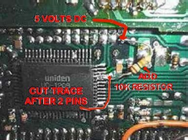
After you remove the board you will see a 4 sided surface mount
chip UC-1208 that has 64 pins.
Look to the right of the chip and locate the 4th and 5th pins from
the top right of the chip(pins 28 and 29).
Notice they are soldered together and run to a trace to a surface mount
resistor.
Carefully cut the trace next to the 2 pins.
In some cases, you may have to unsolder the pins from the pad, because
there is a trace that connects to the pad
that goes under the IC. (So just cutting the outside trace will not be
enough, the pins will still be connected to ground)
NOTE: BE CAREFUL, THE PINS ON THE MICRO ARE BRITTLE AND MAY SNAP IF BENT TOO MUCH.
(I suggest unsoldering the pins, and carefully lifting the pins and
sliding a mica insulator under the pins, then soldering the
pins to the resistor added in the next step).
Now locate 2 rows
of pins to the top of the chip.
The bottom row last pin on the right has 5 volts DC on it.
Solder a 10K resistor to that pin and to the pins 28 and 29.
Now reassemble the radio and your done.
The radio will now tune 26 MHZ thru 30 MHZ.